How was the vortex tube created

How was the first Vortex tube Created?
What is a Vortex tube?
The Vortex tube is a mechanical device that separates compressed gas into two extreme temperature air currents. It was initially named the Ranque-Hilsch Vortex tube, after the names of the two initial inventors. It is also known by other names including: Ranque tube, Hilsch tube, or Ranque-Hilsch tube. The description of this device was originally described in the US. Patent No. 1952281 by Ranque Georges Joseph. A second US. Patent No. 3173273A was filed by Charles D. Fulton.
According to Charles Fulton US patent – it is defined as an “apparatus for cooling a fluid flowing continuously therethrough comprising a housing body having an opening for admitting a gas, a vortex generator supported in said body and receiving said gas, said generator having a plurality of nozzles and a circular vortex cavity into which said nozzles discharge said gas tangentially, a seal at one end of said vortex cavity, a discharge line communicating with the other end of said vortex cavity, and a smaller line for receiving said fluid to be cooled passing coaxially through said discharge line, vortex cavity and seal.”

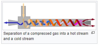
Using fluid dynamic principles and compressed air, the Vortex tube generates gas at very cold and very hot temperatures simultaneously. Compressed air is fed into a compact T-shaped tube with pipes attached to each side. With a simple internal generator, the gas emerging from the “hot” end can reach temperatures of 200 °C (392 °F), and the gas emerging from the “cold end” can reach −50 °C (−58 °F). The owners of this device enjoy an extremely long life with very few issues since the compact device has no moving parts. With the simplistic design and parts, the cost to manufacture and maintain the unit is low. There is also no danger of electrocution or fire. The volume of desired gas flow determines the size of the pipe manufactured. It can be used on any type of gas with consistent results. It is the best, simplest, and most direct method to produce hot and cold air.
The exceptional benefit of the Vortex tube is how little gas pressure is required to produce a large temperature difference in the gas streams.
The requirements for the Vortex tube are:
- Compressed Dry gas (otherwise condensation and freezing of moisture needs to be considered)
- Insulated tube
How Does it Work?
Pressurized gas is injected loosely into a swirl chamber and accelerated to a high rate of rotation. With the tapered shaped nozzle, only the outer shell of the compressed gas can escape at that end. The remainder of the gas is forced to return in an inner vortex of reduced diameter within the outer vortex.

The Vortex tube was first explained by observing the geometrical shape and design of the tube and air flow (turbulence, acoustic phenomena, pressure fields). The Vortex tube effect of the compressed gas motion results from the law of energy conservation. The main physical phenomenon of the Vortex tube is the temperature separation between the cold vortex core and the warm vortex margin. It is best described in several steps:
- The incoming gas is cooled with adiabatic expansion turning any heat into rotational kinetic energy. The total enthalpy is conserved.
Example of adiabatic expansion is when air rises to the atmosphere and expand due to decreased atmospheric pressure allowing the parcel of air to cool. - The peripheral rotating gas moves toward the hot end. Here the heat recuperation effect transfers the heat from the cold slower moving axial flow to the fast moving hot peripheral flow.
- The kinetic energy from the rotating air turns into heat by means of viscous dissipation. As total enthalpy increases from the heat recuperation process – the temperature is raised compared to the inlet gas.
- ome hot gas is exhausted carrying with it excess heat.
- The rest of the gas is funneled toward the cold outlet where more heat is transferred to the peripheric flow. Although the temperature at the axis and at the periphery is about the same everywhere, the rotation is slower at the axis, so the total enthalpy is lower as well.
- This lower total enthalpy gas is “cold” and leaves the cold outlet.
(https://en.wikipedia.org/wiki/Vortex_tube, Retrieved March 8, 2019)
The vortex cooling is due to angular propulsion. As the gas moving towards the center gets colder, the marginal gas in the passage is “getting faster”. The more the gas cools by reaching the center, the more rotational energy it delivered to the vortex and thus the vortex rotates even faster.
Compressed gas at room temperature expands to gain speed through a nozzle. It climbs the centrifugal barrier of rotation during which energy is also lost. That energy is delivered to the vortex, which speeds up the rotating air even more. In a Vortex tube, the cylindrical surrounding wall confines the flow at margins and thus forces conversion of kinetic into internal energy, which produces hot air at the hot exit.
The limiting factor for producing the extreme temperatures is high gas pressure to create the extreme temperature changes in the tube.
Who Invented and Improved the Vortex tube?
Georges-Joseph Ranque (7 February 1898 – 15 January 1973) was the inventor of the Ranque-Hilsch Vortex tube. He was born in France in 1898. At a young age, Georges became interested in physics. In Paris, he studied physics at the Ecole Polytechnique. Afterwards, he pursued a postgraduate degree at the Conservatoire des arts-et-métiers. His initial interest in the operation of the Pantone carburetor led him to study vortices. One of the applications he used the vortex effect was a vacuum pump. His intention was to use his invention to remove dust from a steel plant. While studying the flow of air through a pump, he inserted a cone at one end of the tube, where air was flowing in a vortex and discovered that the stream of air could be split: one hot and the other cold. In 1931, he filed the US. Patent No. 1952281.
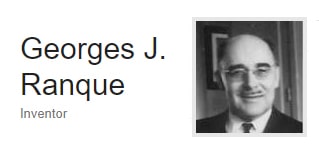 wikipedia: Georges-Joseph Ranque (7 February 1898 – 15 January 1973)
Ranque described his tube as having a counter flow and a uniflow type. Through his research he determined that the counter flow tube was more efficient. The counter flow Vortex tube consisted of:
- A long slender tube with a diaphragm closing at one end of the tube and a small hole in the center of the diaphragm.
- One or more tangential nozzles piercing the tube inside the diaphragm
- A throttle valve at the far end of the slender tube.
On the other hand, the uni-flow Vortex tube is similar in structure to the counter-flow Vortex tube, the significant difference is that the uni-flow tube has two exit holes in the same end. This tube appears to have lower efficiency than the counter-flow tube because of the mix of cold and hot temperature flows at the same exit. Since Ranque’s discovery, the Vortex tube has been the subject of much research and study by the scientific community. The primary focus of research was to determine the factors that caused the thermal separation and to improve the performance of the tube.
Ranque saw the commercial potential of the tube he called “Vortex tube“, which means “tube tourbillion” in French. Unfortunately, compressed air systems were not reliable at the time of this invention. The initial Vortex tube was a commercial failure and Ranque’s firm closed a few years afterwards. He continued to work on other fields of research and the initial discovery of the Vortex tube slowly faded.
The Vortex tube would have remained forgotten if it was not for Rudolf Hilsch, a German physicist, professor, and manager of the Physics Institute of George August University of Göttingen, who is credited with improving the understanding and performance capabilities of the Vortex tube. The important research reported in his 1947 paper, Die Expansion von Gasen im Zentrifugalfeld als Kälteprozeß, emphasized that considerable cooling can be achieved by using the Vortex tube in various applications including refrigeration and cryogenics. He cited Ranque’s work in the paper but because of a printing error in the footnote, it was difficult for other scientific researchers to locate the previous research. Therefore, the Vortex tube was briefly known as the Hilsch tube. Now, the importance of this paper allowed Hilsch’s name to be included in the name of the tube so that it is now known as the Ranque-Hilsch tube.
wikipedia: Ranque-Hilsch vortex tube
In May, 1947 William Taylor of the National Bureau of Standards published Vortex tube experimental results that described another hypothesis of how the tube works. When compressed air passes through the entry nozzle, it speeds up and loses heat. The velocity gained results in a loss of heat energy. This fast, cold air is then slowed as it spirals in the tube. The molecules of gas drop to the center of the tube. Surprisingly, instead of heating up as they lose speed, they pass their energy to the next outer layer and remain cool. The additional cooling effect is caused by the centrifugal force of the whirlpool. The centrifugal force “throws air molecules” out from the center so that there are fewer molecules and lower pressure. When the air molecules move from the high-pressure region of the tube to the lower pressure region in the center of the tube, the gas expands and cools.
- Westley published a comprehensive bibliography of the Vortex tube in 1954, containing brief development of the tube from 1931-1953.
In 1961, a General Electric engineer, named Charles Darby Fulton studied the Vortex tube carefully and developed it for commercial applications. Between 1952 and 1962 he obtained the following U.S. Patents related to the development of the Vortex tube:
- US2603535A: Liquid spray nozzle Filed July 15, 1952 INVENTER David C. Ipsen, Charles D. Fulton.
- US3208229A: VORTEX TUBE Filed Jan. 28, 1965 2 Sheets-Sheet 2 INVENTOR. CHARLES DA FULTON
- US3173273A: VORTEX TUBE Filed March 16, 1965
The goals of the US. Patent No. 3173273A were to:
- provide improvements in the Vortex tube so that they emit colder gas and a larger fraction of cold gas with increased efficiency for a greater range of applications
- Reduce leaks
- Increased ability to utilize high gas pressures efficiently
- Reduce the cost of manufacturing
His company, Fulton Cryogenics, manufactured Vortex tubes and became the Vortec Corporation in 1968 to expand and improve the Vortex product line for industrial and commercial applications. The Vortex tube was used to separate gas mixtures, oxygen and nitrogen, carbon dioxide and helium. In 1991, the Illinois Tool Works acquired Vortec Corporation to further study the Vortex tube for technological applications.
Research for nozzles lead to improvements in the Vortex tube design. Merkulov recommended the tip area being 9% of the cross-section of the tube “with the axial width to be twice the radial depth.” He also inserted a cross in the tube and ultimately shortened the length of the Vortex tube and he received a US patent in 1968 (patent number US3522710A – F25B9/04).
The optimum length of the hot end suggested by Merkulov was 8 to 10 Dc (tube diameter). In 1961, Dr. Parulekar published a paper based on a short Vortex tube:
- A cylindrical or convergent piece of axial length equal to 6 mm.
- A divergent truncated cone with axial length equal to 18mm.
- Cover, which also forms the third part of the hot side is cylindrical and of axial Length equal to 20mm.
Research results determined that the roughness of the internal surface did not affect the results of the tube output – http://engineering-completed-project.blogspot.com/2015/02/project-on-vortex-tube-refrigeration.html
In 2001, Guillaume and Jolly performed a study on a two stage Vortex tube where the cold air from the first tube was injected into a second Vortex tube. They reported that the temperature difference at each stage was greater than would be generated from a single stage Vortex tube.
To optimize the performance of the Vortex tube, multi-stage Vortex tubes have been studied. Dincer in 2011 tried a “three-fold type and six cascade type Vortex tube systems” consisting of three and six Vortex tubes connected in a series. Through this research, the greatest temperature drop occurred when six-cascade Vortex tubes were connected.
The curved Vortex tube, studied by Valipour and Niazi in 2011, proved that an increased in temperature difference was influenced by the curvature of the tube. The maximum refrigeration capacity occurred at 110-degree curvature. The maximum temperature difference was generated by a straight Vortex tube.
Other types of Vortex tubes that have been studied include Vortex tubes in various surroundings, insulated, non-insulted and the types of fluids used – such as water instead of compressed air, oxygen, methane and other gas mixture.
Experimentation Discoveries
Ranque discovered through extensive experiments that when the compressed air enters through the tangential nozzle and expanded cold air discharges through a small hole in the diaphragm. Simultaneously, hot expanded gas is discharged through the valve. The coldest gas is produced only when a small fraction of the gas is released through the small hole. It is recommended that the valve is opened widely for this to occur. The result is the hot gas cools to become warm gas. The hottest gas is achieved by closing the valve. Then, nearly all the gas is released through the small hole and is cool.
The two major inefficiencies of this design are:
- Only a small fraction of the gas can be extracted at the lowest temperature
- The amount of temperature depression obtained never approaches that of an ideal expansion engine.
Continued research is required to determine the optimum configuration is complicated and challenging. There could be up to fifteen factors that need to be considered when optimizing the design. Here are a few:
- kind of gas
- gas pressure
- temperature
- rate of flow
- cold fraction to be delivered at a certain lower pressure
The research on Vortex tube also involves the compressible fluid dynamics of turbulent and unsteady flow, thermodynamics, and heat transfer. Westley stated, “Besides its possible importance as a practical device, the Vortex tube presented a new and intriguing phenomenon in fluid dynamics”.
Each of the above factors results in a change in condition for the remaining factors. Research to determine the optimized factors of using a Vortex tube continues because of the fluid and dependent nature of research results.
Applications of the Vortex tube
The Vortex tube invention impacted refrigeration, air conditioning, cryogenics, instrumentation, and controls. The Vortex tube excels in situations such as cooling a worker wearing a protective suite or electronic equipment in extraordinary hot environment. Research is often placed on cold gas because of its greatest importance and number of uses. Vortex tubes are useful where sometime heat and sometimes cooling of persons or work environments are required. When using a Vortex tube, it is understood that when cold gas is generated, hot gas is also a bi-product.
Nex Flow strives for excellence and improvements in the Vortex tube technology and original design to best suite an application. Nex Flow provides three standard sizes of the Frigid-X® Vortex tubes:
- Mini size – uses 2, 4 or 8 SCFM
- Medium size — uses 10, 15, 25, 30 and 40 SCFM
- Large sizes — uses 50, 75, 100 and 150 SCFM.
Depending on the temperature and pressure the compressed air used, it is possible to achieve cold end temperatures as low as – 40 (-40 C) and even – 50 degrees F (-45.56 C). Vortex tubes are used to cool electronics, machine operations, tools, CCTV cameras, soldered parts, gas samples, and heat seals. Contact Nex Flow expert technicians to help you decide the best Frigid-X® Vortex tubes for your application.
Related posts

What is the Difference between pneumatics and hydraulics?

How to easily Calculate the Cost of your Compressed Air

Ring Vac (Air Operated Conveyor) Compatibility to Convey Different Types of Materials

How is Compressed Air used to Package Products?

Vortex Tubes: Solution to Refrigerants’ Flammability and Cost Issues

Which is best for venting? Air Amplifiers or Ring vacs??